
 1105
1105
This document, and the content contained herein, is intended for customers, users and other persons with the operation and features of the covered Hegla products. While Hegla makes every effort to include accurate and useful information, it is not possible to anticipate or address every possible situation or to account for conditions at unknown locations or interactions with unknown systems or components. Therefor, these documents must be used only for informational purposes and used in conjunction with best practices and with due care. Hegla shall not be responsible for any injuries or losses that occur as a result of the information in this document. Moreover, as products and offerings change over time, the usefulness of the information in this document may become obsolete. It is the responsibility of the reader or consumer to ensure that the information contained herein is timely and reflects the current reality of Hegla products and offerings. Hegla disclaims any and all warranties regarding the information in this document.
***Read chapter 1 of your operators manual before undertaking any work in the area of the linear drives equipment.***
When in doubt please contact Hegla service before taking action (404) 763-9700

Before you set the Grinding head you must ensure that the cutting head adjustment is correct.
To do this follow the instructions in the Strip Test Document.
Only once this has been done and the cutting results are good you can start with adjusting the grinding head.
To ensure that the grinding is within tolerance and that the cut to grind is also within tolerance it is necessary to carry out a test sheet. If the grinding looks like the drawing below then the grinding wheel middle point is not in the middle of the turning axis.

Checking the turning point of the grinding wheel The wheel must turn on the spot when the Z-Axis turns as below. If the spot moves then the wheel is mechanically not centralized. In this case follow the instructions below.
Setting the turning point of the grinding wheel on a Rapidline
- Remove the 20mm wheel.
- Use a feeler to measure the distance between the base plate and the mounting plate as shown in Pic.1.
Pic.1.

- Loosen the grub screw holding the mounting plate in place (Pic.2).
Pic.2.

- Adjust distance as required by moving mounting plate back or forward, and then tighten grub screw back up.
- Now mount the new grinding wheel.
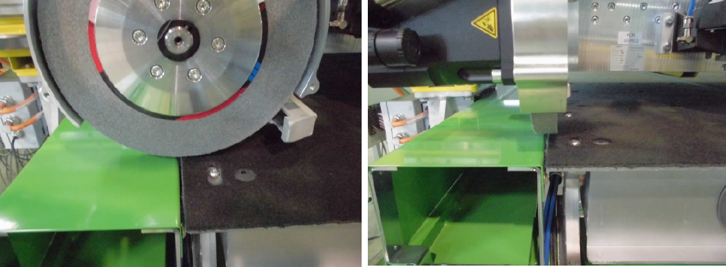
Check that the turning point is the middle of the grinding wheel. You can test this over a fixed point as seen in Pic.3 & 4.
Pic.3. Pic.4.

Now you can set the parameters in the C:\stdmmi\Hegla.ini
[DIN-Vorspann]
Z16=G93 X-104.5 Y254.5 T1 (X- and Y-Offset cutting wheel to grinding head**Your values may vary**)
[BreiteSchleifScheibe]
WKZ_Offset_X=0 (Not used see DIN-Vorspann)
WKZ_Offset_Y=0 (Not used see DIN-Vorspann)
Breite=20 (Grinding Wheel Diameter)
Change measurements accordingly and save the file. You will need to restart the HMI for the changes to take effect and make a NEW cutting plan.
Test result by cutting and grinding squares. Measure grind to grind and ensure that the cut is in the middle of the grind.

