6304
6304
This document, and the content contained herein, is intended for customers, users and other persons with the operation and features of the covered Hegla products. While Hegla makes every effort to include accurate and useful information, it is not possible to anticipate or address every possible situation or to account for conditions at unknown locations or interactions with unknown systems or components. Therefor, these documents must be used only for informational purposes and used in conjunction with best practices and with due care. Hegla shall not be responsible for any injuries or losses that occur as a result of the information in this document. Moreover, as products and offerings change over time, the usefulness of the information in this document may become obsolete. It is the responsibility of the reader or consumer to ensure that the information contained herein is timely and reflects the current reality of Hegla products and offerings. Hegla disclaims any and all warranties regarding the information in this document.
***Read chapter 1 of your operators manual before undertaking any work in the area of the servo motor and drive equipment.***
When in doubt please contact Hegla service before taking action (404) 763-9700

Mechanical adjustment Optimax Plus cutting bridge (without shaft)
Attention-Taper locks on Optimax and Formline gearboxes can be frozen in place with corrosion. The best option for a gearbox that won't let the shaft loose is complete replacement.
Bolts connecting base plate and bridge

1. Drive the bridge on to the zero point and leave the machine switched on so that the motor holds the bridge in position. DANGER-ensure that no one can drive the bridge whilst work is being carried out! It is always best to turn the override of the machine down to 0% by following the Changing the speed of the machine document. Once override is set to 0% and the safety circuit is not broken, the mark the position of the bridge.
2. Release the screws of the taper lock on the motor (on the opposite side to the zero point of the table) until you can turn the taper lock.
3. Loosen the bolts that hold the bridge on the base plate (on the zero point side of the bridge) on the opposite side to the side where you released the taper lock.
4. Now you can move the bridge so that it is parallel to the glass / buffers e.g. the glass is ½ inch (5 mm) off center then you move the bridge ¼ inch (2.5 mm).
5. Tighten the taper lock up, attention make sure that the position of the bridge does not move during this procedure.
6. Tighten the bolts on the base plate up, attention make sure that the position of the bridge does not move during this procedure.
7. Ensure that there is no play between the pinions and the flange of the motor and that the pinions are positioned correctly in the rack.
Software:
This is only necessary after changing one of the motors on a gantry axis (Optimax plus) or the first time the machine is installed. You must reset the Synchronoffset ! To do this you need to do the following: After starting up the machine : !! DO NOT ACKNOWLEDGE THE E-STOP!! !! DO NOT ACKNOWLEDGE THE NC FAULT !! !!This will cause mechanical damage to the bridge if done before setting the Synchronoffset !!

- Plug the Communication module “Lenze LECOM A/B” onto the X-Axis Master drive.
- Link the Communication module via the system cable (RS 232) with the PC (COM 1).
- Start the program Global Drive Control. Start -> Program Files -> Global Drive Control -> Global Drive Control or use the Desktop Icon.
- Activate the soft key Search (you can stop the search as soon as the drive has been found).
- Read the value in the window Pos-ACTPOS and write it down.

- Now change the cable to the X-Axis Slave.
- Activate the soft key Search (you can stop the search as soon as the drive has been found).
- Read the value in the window Pos-ActPos and write it down.
- Now you can close the Global Drive Control software.
Open the Service window (shift F3) and press the green check mark (if password needed use STDMMI)

Press F12 to change into Diagnosis

Then push F6 “machine data” and then F6 “edit machine data” Go down the list until you reach the MK_SYNCHRONOFFSET

Now you take the values you wrote down and subtract X-Axis Master from X-Axis Slave (you must be careful by negative values)
Slave – Master = MK_Synchronoffset
- Enter the value in the MK_syncronoffset and push ENTER and the green tick button.
- Reference the machine. • Push the E-Stop and Push the bridge to the edge of the glass (Zero Position).
- Then go back into the diagnosis and set the MK_METRISCH from inch to mm (only by inch machines).
- Then go to the MK-Grundoffset and set the value for the X-Axis (the first value) to 0.!! When changing the MK_ *** Values you must always push ENTER and the green tick button to accept the new value !!
- Acknowledge the E-Stop. • Change to the F9 window “Set-up” and read the value for the X-Axis (write it down).
- Go back into the Diagnosis screen and enter the value you wrote down in the MK-Grundoffset for the X-Axis (first value).
- Go back into the MK-Metrisch and change back to inch (inch = 0, mm = 1) !! When changing the MK_ *** Values you must always push ENTER and the green tick button to accept the new value !!
The axis should now show position 0 on the screen and be in the corner of the glass! Now you can test the machine.
Adjustment of the height of the cutting bridge:
1.0

- The distance 1.4 between the guide rail (1.1) and the milled surface (1.2) under the cutting bridge must be equal to each guide roller

2.0

- To adjust the height release the nut (2.1)
- Take the special wrench (1.5) and turn the ring 1.3 in the rollers
- The ring is eccentric and by turning the distance will change about +/- 1mm
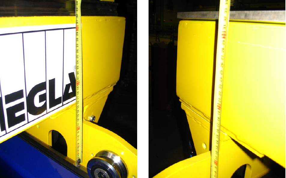
- Take a tape measure and measure the distance on each site of the bridge (see pic 3.0/3.1)
- Adjust the bridge by turning the ring up or down
- If the result is OK, then tighten the nut again
3.0 3.1