
 738
738
This document, and the content contained herein, is intended for customers, users and other persons with the operation and features of the covered Hegla products. While Hegla makes every effort to include accurate and useful information, it is not possible to anticipate or address every possible situation or to account for conditions at unknown locations or interactions with unknown systems or components. Therefor, these documents must be used only for informational purposes and used in conjunction with best practices and with due care. Hegla shall not be responsible for any injuries or losses that occur as a result of the information in this document. Moreover, as products and offerings change over time, the usefulness of the information in this document may become obsolete. It is the responsibility of the reader or consumer to ensure that the information contained herein is timely and reflects the current reality of Hegla products and offerings. Hegla disclaims any and all warranties regarding the information in this document.
***Read chapter 1 of your operators manual before undertaking any work in the area of the linear drives equipment.***
When in doubt please contact Hegla service before taking action (404) 763-9700

DC Bus Under Voltage (Zwischenkreis Unterspannung) Error
Each drive module is connected to a backplane (base plate), to remove the drive module follow the steps below:
- Switch off the machine main power off. Attention-Ensure all power is off before proceeding (480v)!
- Remove all cable connections to drive module.
- Push blue bar down to unlock and pull drive module out of backplane.

Check UG+ and UG- connections on all backplanes.
- ALL screws must be secure.
- The push bar connections must be visible from one drive to the other.
- All push bar connections are connected from right to left, the levers of the bars are on the left hand side of the drive backplane. Exception to the rule is the first left hand drive, as there is no further drive to connect to.


- All screws must be secure on both sides (top and bottom).

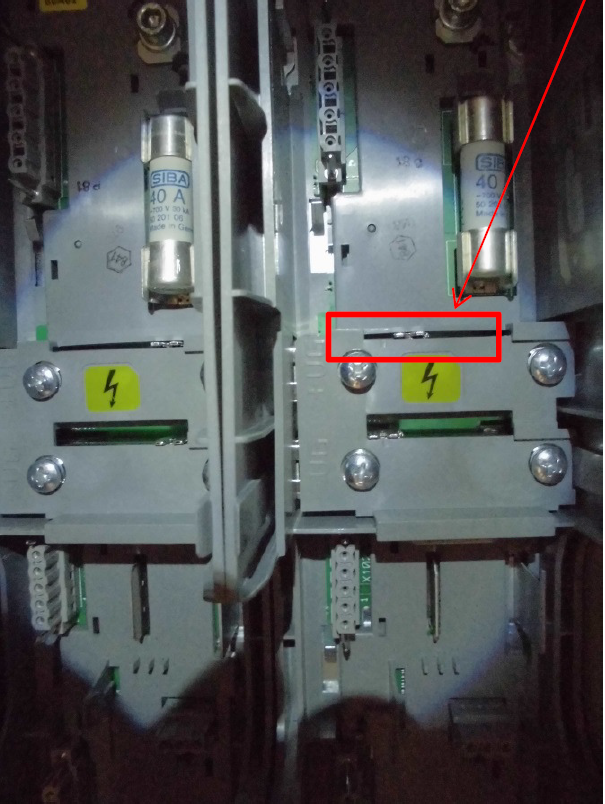
- The connection bars top and bottom must be visible between each drive and the levers must be all the way over to the left.


***Example of bad connection!***
• Top lever not all the way to the left side.
Drive Module Connections
- Check that the drive module connections to the backplanes are good

- Check three phase connection to backplanes on all drives, all three phases must be connected, compare to E-Plan.

- Check all Fuses are good, remove from base and measure Ohm.

Checking the brake module
- Check the connection to the brake module is correct and that the brake module is not burnt out (measure Ohm and compare to E-Plan).

- If all is good re-install all drive modules, re-connect all cables and switch machine on.

